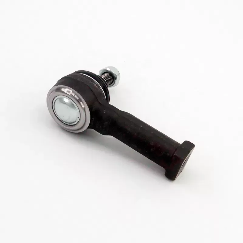
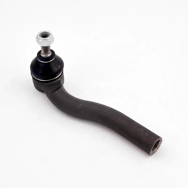
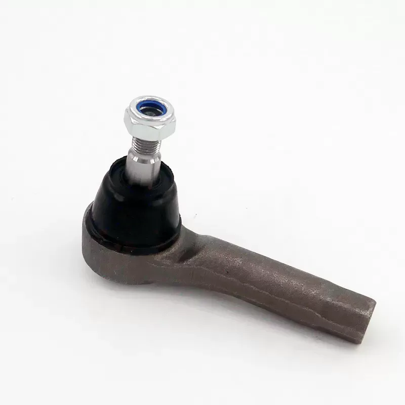
Tie rod ends are commonly made from forged or cast steel, heat-treated alloy steel, carbon steel, stainless steel, sintered metal, engineering polymers, rubber, thermoplastic elastomers, PTFE-based liners, protective coatings, and grease. Each material serves a different purpose: load-bearing metals resist steering forces, bearing surfaces control wear and friction, while boots and coatings protect against water, salt, dust, and temperature changes.
When I evaluate what materials are used in tie rod ends and why do they matter, I look beyond the visible metal housing. The material combination affects tensile strength, fatigue life, impact resistance, corrosion resistance, friction, temperature tolerance, steering feel, tire wear, and replacement intervals. A tie rod end that works well on a dry commuter vehicle may not be suitable for a salt-exposed truck, an off-road vehicle, or a modified suspension system.
This guide explains the function and location of tie rod ends, compares inner and outer designs, examines each major material, and provides a practical step-by-step buying method. I also include quality-control questions that professional buyers can ask a Tie Rod End Supplier, including Zegao Machinery, before approving a production or aftermarket order.
!
Key Takeaways
- Forged and heat-treated alloy steel usually provide the load capacity required for steering and alignment control.
- Bearing surfaces, liners, grease, and boots determine wear resistance more directly than housing material alone.
- Stainless steel and protective coatings reduce corrosion risk but do not automatically improve fatigue strength.
- Inner and outer tie rod ends occupy different steering positions and should not be compared as identical parts.
- Material selection must match daily driving, salt exposure, heavy trucks, off-road impacts, or modified geometry.
- Replacing worn tie rod ends normally requires a wheel-alignment check to restore correct toe settings.
What You Need Before Starting
Before selecting tie rod ends by material, I recommend collecting the vehicle identification number, axle position, steering type, original-equipment part number, thread dimensions, taper dimensions, and the intended operating environment. A parts catalog may list the same vehicle model with different inner and outer tie rod ends, engine options, steering racks, or production years. Matching only the vehicle name can therefore produce an incorrect part.
You should also identify whether the vehicle uses a rack-and-pinion steering system or a steering box with a center link and drag link. Passenger cars commonly use an inner tie rod connected to the steering rack and an outer tie rod end connected to the steering knuckle. Heavy trucks may use related but differently shaped steering joints, so the correct material comparison must include the joint’s position, load direction, and service duty.
For a supplier review, I would request the following information before purchasing:
- Material designation for the ball stud, housing, nut, and bearing liner.
- Heat-treatment process and hardness range for load-bearing components.
- Surface coating or plating type and corrosion-test method.
- Boot compound, temperature range, ozone resistance, and clamp design.
- Grease specification, fill quantity, and operating-temperature range.
- Dimensional inspection records for taper, thread, stud diameter, and articulation angle.
- Lot traceability, sampling plan, and nonconformance handling procedure.
- Packaging method, minimum order quantity, production lead time, and replacement policy.
The most useful documents are not broad claims about durability. I prefer a controlled drawing, a material certificate, a heat-treatment report, dimensional inspection results, and a test plan showing which requirements apply to the specific part number.
Step 1 — Identify What a Tie Rod End Does
What to Do
Start by locating the tie rod assembly between the steering rack or center link and the steering knuckle. The tie rod transmits the steering rack’s linear movement to the wheel, allowing the wheel to turn left or right. The threaded section also provides a toe-adjustment interface, which is why even a small change in tie rod length can affect wheel alignment.
The outer tie rod end normally connects to the steering knuckle through a tapered ball stud. Its ball-and-socket design permits steering movement while allowing the suspension and steering linkage to move through changing angles. The inner tie rod is positioned closer to the steering rack and typically connects to the rack through an articulated joint, often protected by a rack boot.
The tie rod end is not the same as a control arm or ball joint. A control arm primarily locates the wheel carrier relative to the vehicle body while managing suspension movement, whereas a tie rod transfers steering input and controls toe direction. A ball joint may also use a ball-and-socket arrangement, but it generally connects the steering knuckle to a control arm and carries different loads.
Why This Matters
Material selection only makes sense after the joint’s function is understood. An outer tie rod end may experience combined tension, compression, bending, vibration, and impact loads, while an inner joint may experience repeated angular motion and forces transmitted through the rack. The correct material must therefore support both strength and controlled articulation.
A failed tie rod end can create steering looseness, delayed response, uneven toe change, or severe directional instability. In extreme cases, separation of the ball stud from the housing can cause loss of effective steering control at one wheel. That is why the material and manufacturing process must be assessed as safety-related decisions rather than cosmetic differences between replacement parts.
Common Mistakes to Avoid
- Confusing steering and suspension joints: A visually similar ball joint may have a different taper, load rating, articulation angle, or stud orientation.
- Ignoring the inner joint: Replacing only the outer end will not correct looseness that originates inside the rack boot.
- Skipping alignment after installation: Changing the threaded position can alter toe, even when the new part has the correct dimensions.
- Using visible finish as proof of strength: A polished or plated surface does not confirm the core material or heat-treatment condition.
Step 2 — Compare Inner and Outer Tie Rod End Materials
What to Do
I compare inner and outer tie rod ends separately because they do not perform identical work. The outer joint usually has a ball stud, socket housing, bearing seat, dust boot, grease, and threaded shank. The inner joint may use a rack-end ball-and-socket structure, a housing connected to the steering rack, a spring-loaded seat, and a bellows boot.
For tie rod end ball stud materials, common choices include medium-carbon steel, forged alloy steel, and heat-treated steel grades designed to maintain strength after machining. The stud normally requires a controlled combination of tensile strength, surface hardness, core toughness, and fatigue resistance. If the surface is too soft, wear can accelerate; if the component is excessively hard without sufficient toughness, impact damage or cracking risk may increase.
The outer housing may be forged steel, ductile iron, cast steel, or another specified metal depending on the design. A forged housing can provide directional grain flow and good resistance to repeated loading, but the final result still depends on forging quality, machining accuracy, heat treatment, and inspection. Inner rack-end housings may prioritize compact packaging, accurate articulation, and stable preload rather than the same external geometry as an outer end.
Why This Matters
The inner and outer joints can fail in different ways. An outer tie rod end may develop ball-stud looseness, damaged threads, boot leakage, or taper wear, while an inner joint may show rack-end play, abnormal movement under steering load, or wear that is difficult to see without removing the bellows boot. The replacement decision should therefore follow a mechanical inspection rather than a blanket rule that both parts always need replacement.
I do not treat “steel” as a complete material specification. Two steel parts can differ substantially in carbon content, alloying elements, grain structure, hardness, tensile strength, coating, and heat-treatment depth. A supplier should identify the actual grade or an approved equivalent, along with the applicable drawing requirements.
Common Mistakes to Avoid
- Assuming inner and outer ends use the same specification: Their geometry and load paths may differ.
- Selecting by thread size alone: Thread dimensions do not confirm taper fit, stud length, articulation angle, or load capacity.
- Over-tightening the ball-stud nut: Excess torque can damage threads or distort the joint; the vehicle service manual should control torque.
- Failing to inspect the rack boot: A torn boot can allow water and abrasive particles to reach the inner joint.
Step 3 — Evaluate the Main Tie Rod End Materials
What to Do
The most common load-bearing material is forged steel, especially where the component must resist repeated steering forces and impact loads. Forged steel tie rod ends are formed under controlled pressure, then machined and often heat-treated to achieve the required geometry and mechanical properties. Forging can reduce internal porosity compared with some casting processes, but it does not eliminate the need for metallurgical and dimensional inspection.
Heat-treated alloy steel is frequently selected for the ball stud and shank because chromium, molybdenum, nickel, or manganese additions can support hardenability and fatigue performance. A supplier may use induction hardening, carburizing, quenching, tempering, or another process depending on the design. Typical engineering targets may include a hardened wear surface with a tougher core, but the exact hardness range must come from the part drawing rather than a universal number.
Carbon steel can be suitable for many standard passenger-vehicle applications when its grade, heat treatment, and surface protection are properly controlled. It is often less expensive and easier to form than more highly alloyed grades. Its main limitation is that unprotected carbon steel has greater exposure to oxidation, especially in areas where paint, plating, or phosphate treatment is damaged by stone impact.
Chromoly steel, generally associated with chromium-molybdenum alloy systems, is selected when designers require a favorable combination of strength, toughness, and fatigue resistance. It can be relevant to heavy-duty, off-road, competition, or modified applications, but the label alone is not enough to establish suitability. I would still verify the grade, heat-treatment cycle, tensile data, fracture inspection, and compatibility with the steering geometry.
Stainless steel provides better resistance to moisture and chloride exposure than ordinary carbon steel, depending on the specific grade and surface condition. It can be useful for corrosion-resistant tie rod ends in coastal areas, winter-salt regions, or applications where surface oxidation is a major concern. Stainless steel may have different hardness, galling, thermal-expansion, and strength characteristics, so corrosion resistance should not be confused with higher load capacity.
Sintered metal may be used for bearing elements, seats, or wear components rather than the entire tie rod end. Powder metallurgy allows controlled porosity and can support oil retention in selected applications. However, the material must be designed for the actual contact pressure, articulation range, contamination exposure, and lubrication method; a sintered insert that performs well in a protected joint may not be suitable for severe abrasive exposure.
Bearing surfaces can include hardened steel against a polymeric liner, a steel ball against a synthetic insert, or a metal seat with a controlled preload. The bearing interface determines contact stress, friction, wear rate, and the amount of free play that develops over time. I pay particular attention to surface roughness, hardness depth, liner thickness, and whether the design is intended to be lubricated or maintenance-free.
PTFE-based liners and other composite bearing materials can reduce friction and provide smooth articulation without frequent grease service. Some designs use glass-fiber or fabric reinforcement to control creep under load. These materials may perform well in low-maintenance applications, but excessive heat, chemical exposure, dirt intrusion, or incorrect preload can shorten their service life.
The boot compound is another important material decision. Natural rubber, nitrile rubber, chloroprene rubber, EPDM, and thermoplastic elastomers each have different resistance to oil, ozone, ultraviolet exposure, cold temperatures, and repeated flexing. A boot that remains flexible but does not seal correctly can still permit contamination into the bearing, so I evaluate the compound together with the clamp design and sealing lip geometry.
Protective coatings may include zinc plating, zinc-nickel plating, phosphate treatment, e-coat, painted systems, or specialized conversion coatings. Corrosion performance should be confirmed through a defined test method, such as neutral salt spray testing under ASTM B117 conditions, while recognizing that salt-spray hours do not directly equal vehicle service years. Coating thickness, adhesion, edge coverage, thread protection, and stone-impact resistance also influence field behavior.
Grease and lubrication materials control friction and wear at the ball-and-socket interface. A suitable grease must maintain film strength across the expected temperature range and remain compatible with the boot, liner, and metal surfaces. Overfilling, underfilling, using an incompatible solvent, or installing a boot with trapped air can affect sealing and joint movement.
Why This Matters
Each material property addresses a different failure mechanism. Tensile strength helps resist pullout and axial load, fatigue resistance supports repeated steering cycles, impact toughness reduces brittle fracture risk, corrosion resistance protects section thickness, and low-friction liners reduce articulation resistance. No single material is automatically the best for every tie rod end.
A useful material comparison should include the complete assembly rather than only the stud. For example, a forged alloy-steel stud paired with a poorly sealed boot may fail earlier than a carbon-steel stud with accurate heat treatment and effective contamination control. The performance of the joint is a system result created by metal, bearing surface, lubricant, seal, coating, and manufacturing tolerance.
Common Mistakes to Avoid
- Choosing aluminum only to reduce weight: Aluminum has lower density than steel but requires careful design to achieve comparable thread strength, fatigue performance, and impact resistance.
- Treating chromoly as a guarantee: Alloy content does not replace heat-treatment control or proof testing.
- Ignoring bearing material: Ball-stud strength cannot compensate for excessive liner wear or incorrect preload.
- Assuming stainless steel eliminates maintenance: Water, grit, damaged boots, and joint contamination can still cause wear.
- Comparing salt-spray hours without context: Test duration, coating system, scribe method, and acceptance criteria must be specified.
How Do Tie Rod End Materials Affect Performance?
Material affects tie rod end performance through six connected properties: strength, fatigue life, impact resistance, corrosion resistance, friction, and temperature tolerance. A part with sufficient tensile strength may still perform poorly if its bearing liner wears quickly, its boot hardens in cold weather, or its coating allows corrosion at a threaded section.
For example, a vehicle used in a region with winter road salt may need a more complete corrosion-control system than a vehicle operated in a dry climate. The relevant solution could combine plated steel, sealed boot geometry, corrosion-resistant clamps, and grease compatibility rather than simply replacing steel with stainless steel. In an off-road application, impact resistance, articulation angle, boot protection, and resistance to abrasive dust may be more important than a low purchase price.
Temperature tolerance also influences material selection. Under-hood heat, brake heat, cold-weather stiffness, and rapid temperature cycling can change rubber flexibility and lubricant viscosity. A boot that remains flexible at approximately −40°C may use a different compound from one optimized for moderate passenger-car temperatures, and the supplier should provide a specified operating range rather than an unsupported general claim.
Step 4 — Match Materials to the Driving Environment
What to Do
For daily drivers, I normally prioritize correctly specified steel, controlled heat treatment, a sealed bearing interface, a flexible boot, and verified dimensional compatibility. The vehicle’s original load requirements and steering geometry should remain the reference point. A more expensive material offers limited value if the replacement has an incorrect taper, inaccurate thread length, or poor boot sealing.
For winter and coastal use, I focus on corrosion-resistant tie rod ends with protected steel surfaces, sealed boots, and corrosion-resistant fasteners where specified. I ask whether the coating was tested after threaded assembly and whether the ball stud’s exposed taper and nut interface received appropriate protection. I also inspect the boot for ozone cracking because a split boot can allow saltwater and grit to reach the bearing.
Heavy trucks require attention to larger joint dimensions, higher static and cyclic loads, articulation, and service conditions. I would request load data, fatigue-test procedures, grease requirements, and inspection records for the specific commercial-vehicle application. A passenger-car replacement should never be substituted merely because its thread diameter appears similar.
Off-road vehicles may experience sharp impacts, high articulation, water crossings, mud, dust, and modified ride height. In this environment, the material choice must be evaluated with boot shielding, joint angle, stud diameter, housing clearance, and suspension travel. A harder component is not automatically safer if the modified geometry creates side loading outside the original design envelope.
Motorsports and drifting applications place repeated shock loads and rapid steering inputs on the linkage. Some competition parts use stronger alloy steels, larger studs, replaceable spherical bearings, or adjustable designs, but these features may increase noise, vibration, maintenance, and inspection requirements. I recommend selecting a component based on the rules, expected duty cycle, and inspection schedule rather than using a racing material on a street vehicle without a clear reason.
Modified suspension geometry needs special caution because lowering, lifting, extended arms, altered steering arms, or increased wheel offset can change joint angles and leverage. The original tie rod end may experience loads that were not present in the factory configuration. Before selecting a material, I would verify articulation limits, bump-steer behavior, clearance through suspension travel, and whether the joint is approved for the modified geometry.
Why This Matters
A material that survives one environment may fail in another because field loads and contamination are different. Salt accelerates corrosion, off-road dust increases abrasive wear, heavy-truck loads raise fatigue demand, and motorsport impacts can create local deformation. The most appropriate component is the one whose material system matches the actual duty cycle.
Common Mistakes to Avoid
- Buying a competition-style part for normal commuting: Increased stiffness or adjustability may create additional maintenance and noise without reducing ordinary road-service risk.
- Ignoring wheel offset and tire size: Larger tires and altered offset can increase steering loads.
- Using an exposed joint in mud or water: Sealing and boot protection may matter more than a small change in steel grade.
- Skipping periodic inspection after modifications: Modified steering systems should be checked for play, boot damage, fastener movement, and abnormal wear more frequently.
Step 5 — Inspect Symptoms, Safety Risk, and Alignment Requirements
What to Do
I begin with a physical inspection for looseness, torn boots, displaced grease, rust staining, damaged threads, and abnormal movement. Depending on the vehicle design, an assistant can move the steering wheel while the technician observes the inner and outer joints. A dial indicator or approved play-measurement method can provide more repeatable evidence than judging movement by eye.
Common symptoms include steering play, wandering, clunking over uneven surfaces, delayed response, uneven tire wear, and a steering wheel that no longer remains centered. Inner tie rod wear may be harder to detect because the joint is inside the rack boot, while outer wear is often more visible near the steering knuckle. These symptoms can also come from wheel bearings, control-arm bushings, ball joints, tires, or rack mounts, so diagnosis should isolate the actual source.
Tire wear patterns provide supporting evidence but not a complete diagnosis. Excessive toe-in or toe-out can produce feathering across the tread, while looseness can cause changing toe during braking, acceleration, or cornering. If the tie rod end has measurable play, the vehicle may not maintain the intended wheel direction under changing loads.
Why This Matters
A tie rod end failure is a safety issue because the component is part of the steering path. Continued driving with significant looseness can increase tire wear and place additional stress on related steering and suspension parts. If a joint separates, steering control at that wheel may be severely reduced or lost.
After replacing an inner or outer tie rod end, I recommend a four-wheel alignment check when the vehicle configuration allows it. At minimum, the front toe should be measured and adjusted to the manufacturer’s specification, with steering-wheel centering verified afterward. Counting exposed threads can help approximate the original setting, but it is not a substitute for measured alignment.
Common Mistakes to Avoid
- Replacing parts based only on noise: A clunk may originate from several steering or suspension components.
- Driving after discovering severe play: Significant looseness should be treated as a repair priority.
- Assuming one worn side proves the other side is failed: Inspect both sides and replace according to measured condition and service guidance.
- Skipping the alignment: Incorrect toe can consume tires quickly and leave the vehicle unstable even with new joints.
Step 6 — Evaluate a Tie Rod End Supplier
What to Do
When I assess a supplier, I separate product claims from evidence. I request drawings, control plans, material certificates, heat-treatment records, coating specifications, dimensional reports, and samples from the same production process intended for the order. For a safety-related steering part, traceability by batch or lot is important because it connects test records to delivered components.
Useful quality checks include coordinate-measuring-machine verification of critical dimensions, thread gauges, taper gauges, hardness testing, pull-out or proof-load testing, articulation-torque measurement, boot-leakage testing, and fatigue testing. Test standards should be identified where applicable, but acceptance values must come from the part design or customer specification. I would not accept a generic test photograph as evidence for a particular part number.
Delivery risk should be evaluated separately from engineering quality. A buyer should confirm minimum order quantity, normal production lead time, tooling status, packaging quantity, export documents, inspection-release procedure, and the supplier’s process for handling shortages or rejected lots. A 30-day production promise is not useful if critical components, coatings, or packaging materials are not included in that schedule.
Why This Matters
A reliable procurement decision must account for quality compliance, delivery continuity, and total cost of ownership. A low unit price can become expensive if a 2% defect rate creates sorting labor, returns, downtime, or customer claims. For example, on an order of 5,000 pieces, a 2% nonconformance rate represents 100 pieces requiring rework, replacement, or investigation.
Zegao Machinery, also presented as Yuhuan Zegao Machinery, identifies tie rod ends, ball joints, control arms, stabilizer links, and other chassis components within its product range. Its published company information describes a 5,000-square-meter factory, more than 3,000 square meters of construction area, 30 million yuan in fixed assets, 20 million yuan in working capital, and annual output value of 60 million yuan. I would still verify the specific material grades, heat-treatment records, inspection equipment, test results, and delivery terms for each tie rod end program before placing a commercial order.
Common Mistakes to Avoid
- Accepting “OEM quality” without defined criteria: Request dimensional, material, and performance requirements in writing.
- Ignoring packaging validation: Damaged boots, bent studs, and mixed part numbers can create installation failures.
- Using one sample to approve a large order: Approve the production process and establish lot-based inspection.
- Focusing only on purchase price: Include freight, incoming inspection, warranty exposure, sorting, installation, and alignment costs.
Step 7 — Calculate Total Cost of Ownership
What to Do
I calculate total cost using more than the quoted unit price. A practical model includes the part, freight, inspection, installation labor, alignment, expected replacement interval, warranty handling, and the cost of vehicle downtime. The same calculation can be performed for standard carbon-steel, heat-treated alloy-steel, coated, or application-specific assemblies.
Consider an illustrative comparison: a standard replacement costs $28, installation is $90, and alignment is $100, creating a direct repair cost of $218. A second option costs $52 but has the same $190 installation and alignment expense, creating a direct cost of $242. The second option must reduce repeat repairs or downtime by at least $24 per installed side to recover its additional purchase price.
For a fleet ordering 200 tie rod ends, a $6 unit-price difference changes the purchase budget by $1,200. If better lot control reduces incoming sorting from 3 hours to 1 hour per 100 pieces at a labor rate of $35 per hour, the inspection saving is $1,400 across 200 pieces, before considering warranty or downtime effects. These are planning examples, not universal savings; actual results depend on defect rates, labor costs, freight, and service intervals.
Why This Matters
Material selection can influence service life, but service life is also affected by road conditions, alignment, boot sealing, vehicle load, tire size, steering geometry, and installation torque. I therefore avoid promising a fixed mileage figure for every vehicle. Instead, I compare documented test results, field-return data, failure modes, and the cost of replacing the part if the first selection does not meet the application.
A professional buyer should also compare the cost of a delayed shipment. If a vehicle or repair shop loses one day of availability at an internal cost of $300, a 48-hour delivery delay can exceed the price difference between two tie rod end options. Delivery planning, safety stock, and part-number accuracy are therefore part of the material-selection decision.
Common Mistakes to Avoid
- Assuming the most expensive part has the lowest long-term cost: Require evidence that the extra material or process addresses the actual failure mode.
- Leaving out alignment costs: Every steering-joint replacement may require alignment verification.
- Ignoring return logistics: International returns, inspection, and replacement freight can exceed the original unit price.
- Ordering without demand data: Use historical consumption, vehicle population, and lead-time variability to set inventory levels.
Material Comparison Checklist
I use the following checklist when comparing tie rod end materials for vehicle owners, repair shops, distributors, and manufacturers:
| Evaluation item |
Questions to ask |
Why it matters |
| Ball stud |
Is it forged, machined, or cast? What heat treatment is used? |
Affects fatigue strength, impact resistance, and wear |
| Housing |
What steel or alloy is specified? Is the housing forged or cast? |
Influences load capacity and deformation resistance |
| Bearing surface |
Hardened metal, sintered insert, PTFE liner, or polymer seat? |
Controls friction, preload stability, and wear |
| Boot |
Rubber or thermoplastic? What temperature and ozone range? |
Protects against water, dust, salt, and grease loss |
| Coating |
Zinc, zinc-nickel, phosphate, paint, or stainless material? |
Reduces corrosion at exposed surfaces |
| Lubricant |
What grease is used and what temperature range applies? |
Maintains low friction and limits wear |
| Inspection |
Are taper, thread, hardness, torque, and articulation checked? |
Reduces fitment and assembly risk |
| Application |
Daily use, salt, truck, off-road, drifting, or modified geometry? |
Matches the material system to real loads |
Conclusion
What Materials Are Used in Tie Rod Ends and Why Do They Matter? The main materials include forged steel, carbon steel, heat-treated alloy steel, chromoly, stainless steel, sintered metal, hardened bearing surfaces, PTFE or composite liners, rubber or thermoplastic boots, protective coatings, and specialized grease. Their combined properties determine steering safety, alignment stability, corrosion resistance, friction, wear rate, temperature performance, and total service life.
For daily drivers, I would begin with the correct vehicle-specific steel specification, sealed bearing construction, accurate dimensions, and documented corrosion protection. For salt exposure, heavy trucks, off-road use, motorsports, or modified suspension geometry, I would require additional evidence covering fatigue, articulation, impact loading, boot sealing, and coating performance.
My practical next step is to confirm the inner or outer position, obtain the original part number, request material and inspection documents from the Tie Rod End Supplier, and compare total installed cost rather than unit price alone. After installation, inspect fasteners and boots, measure steering play, and complete a wheel-alignment check to confirm that the replacement restores the intended steering and toe settings.


 es
es cn
cn