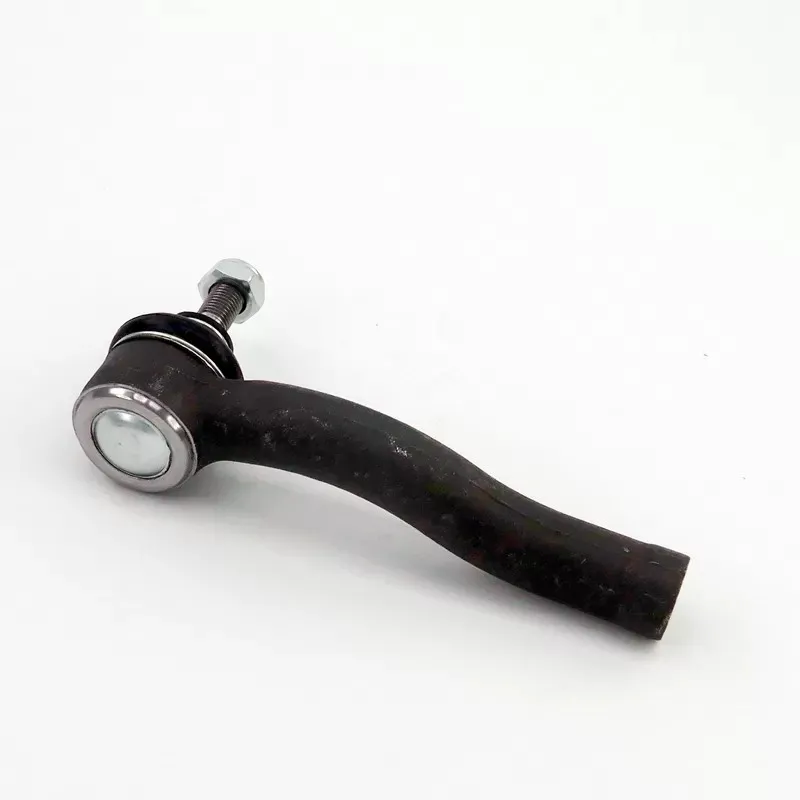
To identify a replacement correctly, I use four checks: identify the rod-end thread, measure stud and taper dimensions, measure assembled eye-to-eye length, then verify thread direction and taper compatibility before ordering. Matching only the visible thread is insufficient because the stud diameter, taper length, steering layout, and adjustment range also determine whether the part fits safely.
Tie Rod End Thread Size and Taper Explained is essential for replacement parts, custom steering fabrication, and workshop inspection. A tie rod end transfers steering movement between the linkage and steering knuckle, so a dimensional mismatch can create loose joints, incomplete taper seating, bottomed-out threads, or insufficient alignment adjustment.
!
I recommend recording every measurement before removing the original part whenever access allows. A written worksheet should include thread diameter, pitch, direction, exposed thread length, stud dimensions, taper measurements, center length, and the original part number or vehicle application.
What Is Tie Rod End Thread Size and Taper?
The tie rod end thread size describes the threaded connection between the rod and the tie rod end. It normally includes the nominal major diameter, thread pitch, and thread direction, such as right-hand or left-hand threading. The taper describes the conical stud section that fits into a matching tapered hole in a steering knuckle, pitman arm, or drag link.
These two dimensions serve different functions. The thread controls how the tie rod end attaches to the adjustment sleeve or steering link, while the taper controls how the ball-stud joint seats inside the steering component. A part can have the correct thread but still fail to fit because its stud diameter, taper angle, or taper length is different.
For example, a 14 mm threaded tie rod end is not automatically interchangeable with every other 14 mm version. One may use a different pitch, such as 1.5 mm instead of 2.0 mm, while another may have a different thread direction or a larger tapered stud. The part number, vehicle application, and complete dimensional profile must therefore be checked together.
Step 1 — Identify Tie Rod End Thread Size, Pitch, and Direction
What to Do
I begin by cleaning the exposed threads with a wire brush and solvent that does not damage the boot or seal. Dirt, corrosion, and flattened thread crests can distort caliper readings and cause an incorrect pitch result. I then measure the outside diameter across the thread crests with a metric or inch-capable caliper.
Next, I determine the tie rod end thread pitch. For metric threads, pitch is the axial distance from one crest to the next, measured in millimeters. A thread-pitch gauge is the fastest method, but I can also measure the distance across 10 thread spaces and divide by 10; for example, 15.0 mm across 10 spaces indicates a 1.5 mm pitch.
For inch-threaded parts, I count threads per inch rather than measuring millimeter pitch. A 1/2-20 thread has a nominal diameter of 1/2 inch and 20 threads per inch, while a 1/2-13 thread has the same nominal diameter but a different pitch. These threads must not be treated as interchangeable because the nut, sleeve, and engagement geometry differ.
I also inspect the thread direction. A right-hand thread tightens clockwise when viewed from the threaded end, while a left-hand thread tightens counterclockwise. Many steering systems use opposing thread directions on the same adjustment sleeve so toe can be adjusted without removing both ends, making direction identification especially important.
Why This Matters
Thread size determines whether the tie rod end can physically attach to the steering link. Thread pitch determines whether the mating nut or sleeve can achieve full engagement without cross-threading. Thread direction determines whether adjustment operates as intended and whether the assembly can resist loosening during service.
I record at least five thread details: nominal diameter, pitch or threads per inch, direction, usable engagement length, and thread condition. The usable engagement length is important because a replacement may have the correct diameter and pitch but a shorter threaded section, reducing adjustment range or leaving too few engaged threads.
The numbers on a tie rod end may refer to an OEM reference, aftermarket catalog number, casting code, or engineering identifier. They do not always directly state thread diameter or taper size. I use those numbers to locate the application, then verify the physical dimensions against the removed component and the steering-system layout.
Common Mistakes to Avoid
- Measuring over damaged threads: Corrosion can increase the apparent diameter; measure several locations and compare the reading with a clean thread section.
- Confusing pitch with diameter: A measurement such as 14 mm identifies approximate diameter, not the thread pitch.
- Ignoring thread direction: A left-hand tie rod end may appear correct until the adjustment sleeve refuses to assemble.
- Using the nut as the only reference: A replacement nut may have a different thread standard from the original component.
- Assuming metric and inch sizes are interchangeable: Similar measurements can still have incompatible pitch and fit.
Step 2 — Measure Tie Rod End Stud and Taper Dimensions
What to Do
After identifying the thread, I measure the tapered stud before selecting a replacement. I clean the stud and inspect it for galling, fretting, impact marks, or deformation. The main taper measurements are the large-end diameter, small-end diameter, and taper length between those two measurement planes.
For a practical measurement, I use a digital caliper with narrow jaws and record the diameter at the widest and narrowest accessible sections of the conical surface. I avoid placing the caliper on a damaged chamfer or on the threaded portion. If the stud has a shoulder, I separately record the shoulder diameter and the distance from the shoulder to the taper transition.
The taper angle can be estimated from measured diameters and taper length. Using the included taper angle, the calculation is:
[
\theta = 2 \times \arctan\left(\frac{D-d}{2L}\right)
]
where D is the large-end diameter, d is the small-end diameter, L is taper length, and θ is the included taper angle. The result is an estimate because worn surfaces, rounded ends, and uncertain measurement planes can produce errors.
For example, assume a stud measures 18.00 mm at the large end, 16.00 mm at the small end, and 24.00 mm across the taper length. The estimated included angle is approximately 4.77 degrees. That example is for calculation practice only; I do not use it as a universal automotive taper specification.
Why Does Tie Rod End Taper Matter?
The tapered stud creates a wedging fit inside the matching tapered hole. When the castle nut is tightened to the specified torque, the stud should seat fully and concentrically rather than contact only at one edge. Correct engagement supports load transfer and limits movement between the stud and steering knuckle.
An incorrect taper may appear to fit because the stud can enter the hole partway. However, the nut may bottom against the unthreaded shoulder before the taper seats, or the stud may sit too deeply and leave insufficient thread above the nut. Either condition can reduce clamping reliability and change the joint’s operating position.
I inspect the mating hole for ovality, burrs, paint, rust scale, and previous damage. The replacement stud must match the hole’s small-end diameter, large-end diameter, taper length, and seating depth. A tapered stud should not be forced into a straight hole, and a straight stud should not be substituted for a tapered steering joint.
How to Identify Tie Rod End Taper
I use three identification methods together: the vehicle or axle application, the original part number, and direct dimensional comparison. Catalog descriptions may state a stud diameter, but the listed diameter may refer to the threaded section, the largest taper diameter, or the ball-stud shank. The measurement reference must be clear before comparing parts.
A taper gauge or dedicated ball-joint measurement tool can improve repeatability, especially when the original part is worn. For a small repair shop, a caliper accurate to 0.01 mm, thread-pitch gauges, a steel rule, and a taper template provide a useful starting set. For production inspection, I would add a height gauge, optical comparator, or coordinate measurement system.
The inspection record should show where each diameter was taken. I use a sketch with arrows marking the small diameter, large diameter, taper length, shoulder height, and threaded length. This prevents two suppliers from comparing different dimensions under the same label.
Step 3 — Measure Center Length and the Actual Steering Layout
What to Do
The required tie rod or drag link length should come from the actual steering-system layout, not from a generic catalog assumption. I measure the distance between the two joint centers, usually from the center of one ball stud or eye to the center of the opposite joint. I record whether each end is a tie rod end, heim joint, rack end, ball joint-style end, or threaded adapter.
For an adjustable assembly, I measure the current installed length before disassembly. I then record the exposed thread on both sides of the adjustment sleeve and count the available adjustment turns. This shows whether the existing assembly is near the middle of its range or already close to a thread limit.
A practical worksheet should include:
| Measurement |
Original part |
Replacement candidate |
Acceptance note |
| Thread diameter |
___ mm/in |
___ mm/in |
Must match mating sleeve |
| Thread pitch |
___ mm / TPI |
___ mm / TPI |
Must match exactly |
| Thread direction |
RH/LH |
RH/LH |
Verify both ends |
| Large taper diameter |
___ mm |
___ mm |
Compare at same plane |
| Small taper diameter |
___ mm |
___ mm |
Check seating depth |
| Taper length |
___ mm |
___ mm |
Confirm hole engagement |
| Stud thread length |
___ mm |
___ mm |
Avoid nut bottoming |
| Center-to-center length |
___ mm |
___ mm |
Measure installed layout |
| Adjustment range |
___ mm |
___ mm |
Confirm alignment reserve |
Why This Matters
A tie rod end does not operate as an isolated component. Its center length changes toe, steering-center position, drag-link geometry, and available adjustment. On a custom suspension, changes in ride height or steering-arm location can alter the required length even when the original vehicle part number is known.
For a tie rod assembly with two adjustable ends, I calculate the target length from the fixed mounting points and the desired joint-center positions. I then check whether the adjustment sleeve provides enough inward and outward travel while retaining the manufacturer’s minimum thread engagement. A visually similar part may leave the assembly at the end of its adjustment range, making alignment difficult.
The correct approach is to separate replacement identification from custom fabrication. Replacement work should reproduce the original application’s thread, taper, stud, and center dimensions unless an engineered modification is specified. Custom fabrication requires a separate review of steering-arm strength, joint articulation, misalignment, clearance, thread engagement, and inspection requirements.
Common Mistakes to Avoid
- Measuring overall length instead of center length: The housing, stud, and threaded protrusion can vary while the joint centers remain the controlling dimension.
- Ignoring the installed angle: A drag link may require a different joint orientation from a straight tie rod.
- Removing both ends before recording adjustment: This can erase the original baseline used for alignment.
- Using nominal rod length only: The end-body length and thread insertion depth also affect the assembled measurement.
- Failing to check suspension travel: The joint must articulate through the full steering and suspension movement without binding.
How Do You Measure a Tie Rod End?
I measure a tie rod end in a fixed sequence: clean the part, identify the thread, measure the stud and taper, record the joint-center length, and compare every result with the vehicle or fabrication drawing. The most useful tools are a caliper, thread-pitch gauge, steel rule, torque wrench, taper gauge, and a camera for recording orientation. I take each measurement at least twice and repeat any result that changes by more than the tool’s displayed resolution.
Before measuring, I mark the left and right sides and photograph the adjustment sleeve, jam nuts, cotter-pin hole, and stud orientation. I also record whether the joint uses a castle nut, prevailing-torque nut, or another retaining method. The replacement must accommodate the correct nut diameter, cotter-pin hole position, washer or spacer arrangement, and available wrench clearance.
For production or wholesale purchasing, I convert the worksheet into a controlled inspection form. A Tie Rod End Supplier should receive the OEM reference, application year and engine, left/right position, thread specification, taper data, center length, packaging requirements, and requested inspection documents. This reduces quotation errors caused by descriptions such as “front tie rod end” without dimensional references.
Step 4 — Verify Thread, Taper, Stud, and Safety Compatibility Before Ordering
What to Do
Before I approve a replacement, I compare the measured data with the supplier drawing or catalog specification. The review covers thread diameter, pitch, direction, threaded length, stud diameter, taper dimensions, taper angle, center length, body orientation, boot design, grease provision, nut type, and cotter-pin position.
I ask for a dimensional drawing when the application is unclear or when the part is intended for a custom steering build. The drawing should identify datum points and tolerances rather than provide only a photograph. If the part is for a fleet or production program, I also request batch identification and a documented sampling plan.
I verify the installation process against the vehicle service information. The castle nut must be tightened to the specified torque, and the cotter pin should be installed through the hole without loosening the nut to align the pin. If the nut reaches torque before the taper seats, I stop and inspect the mating surfaces instead of adding washers or forcing the joint into position.
After assembly, I check for full taper seating, sufficient thread engagement, boot compression, steering clearance, and free movement. I then perform an alignment check and road-test the vehicle only after confirming that no joint binds through the steering range. Any unusual play, clicking, or change in steering-center position requires reinspection.
Compatibility Checklist
| Check |
Pass condition |
Failure indication |
| Thread diameter |
Matches drawing or original specification |
Nut or sleeve will not start correctly |
| Thread pitch |
Same metric pitch or TPI |
Cross-threading or loose fit |
| Thread direction |
Matches adjustment layout |
Sleeve adjusts in the wrong direction |
| Taper |
Stud and hole seat over the intended area |
Nut bottoms before seating |
| Stud length |
Nut and cotter pin align correctly |
Insufficient thread or excess protrusion |
| Center length |
Steering geometry remains within adjustment range |
Alignment cannot be achieved |
| Articulation |
Joint moves through full operating angle |
Binding or boot distortion |
| Retention hardware |
Correct nut, washer, and cotter pin used |
Retaining method is incomplete |
When Thread Size Matches but Taper Does Not
Tie rod ends with the same thread size cannot automatically be interchanged. The thread may connect correctly to the adjustment sleeve while the stud fails to match the steering knuckle. Differences in taper angle, large-end diameter, small-end diameter, stud length, and shoulder height can all prevent correct seating.
This is one of the most common fitment failures in mixed-brand repairs and custom suspension builds. For example, two parts may both use an M14 × 1.5 thread, but one may have a 17 mm tapered stud and the other a 19 mm stud with a different taper length. The thread match solves only one connection in the assembly.
I do not correct an incorrect taper by tightening the nut further. I also avoid machining a steering knuckle or reaming a tapered hole unless the modification is engineered, performed with the correct reamer, and followed by dimensional and safety inspection. For a standard replacement, the safer decision is to select the tie rod end that matches the original application and measured geometry.
Troubleshooting Common Fitment Failures
| Symptom |
Likely cause |
Corrective action |
| Threads stop after one or two turns |
Wrong pitch, damaged threads, or mixed metric/inch standards |
Clean, gauge, and compare pitch before assembly |
| Nut reaches torque but stud remains loose |
Taper does not match or a spacer is misplaced |
Remove, inspect seating surfaces, and verify taper dimensions |
| Adjustment sleeve bottoms out |
Threaded section is too long or assembly length is incorrect |
Recalculate center length and available adjustment |
| Alignment cannot reach specification |
Tie rod or drag-link length is outside the required range |
Measure actual layout and select correct body length |
| Cotter pin cannot align |
Wrong stud thread length or nut style |
Use specified nut and verify stud shoulder height |
| Boot twists during steering |
Joint orientation or articulation range is incorrect |
Check angular movement at full lock and suspension travel |
| Steering feels loose after installation |
Taper not seated, worn mating hole, or under-torqued nut |
Reinspect joint, hole, torque, and retention hardware |
| Sleeve turns but length does not change |
One thread direction is incorrect or the jam nut remains tight |
Verify RH/LH arrangement and loosen jam nuts correctly |
How to Choose the Correct Tie Rod End
I use a six-part selection checklist when choosing a replacement:
- Confirm the vehicle application: Record make, model, year, engine, axle, steering position, and left/right side.
- Match the thread specification: Check diameter, pitch, thread direction, and usable threaded length.
- Match the taper: Compare small diameter, large diameter, taper length, stud shoulder, and seating depth.
- Match the assembled length: Measure center-to-center distance and verify adjustment reserve.
- Check retention details: Confirm castle nut size, cotter-pin hole, washer, boot, and grease fitting arrangement.
- Review supplier documentation: Request drawings, inspection records, batch identification, and packaging details when buying in quantity.
The best ways to identify a tie rod end combine physical measurement with application data. A photograph can confirm general shape and orientation, but it cannot reliably show thread pitch, taper angle, or center length. A part-number search is useful, yet I still compare the catalog dimensions with the original part before placing an order.
For a small repair shop, the cost of a measurement kit is usually lower than the cost of repeated returns, additional alignment labor, and a second vehicle teardown. I would keep a thread-pitch gauge covering common metric and inch standards, a 150 mm digital caliper, a steel rule, a centerline measuring fixture, and a taper measurement template. Each tool should be checked periodically against a known reference or gauge block.
Quality, Delivery, and Total Cost Considerations
When I evaluate a Tie Rod End Supplier, I separate unit price from total procurement cost. The full cost includes sample approval, measurement verification, packaging, freight, customs, inspection labor, installation rework, alignment, warranty handling, and downtime. A part priced $8 lower can become more expensive if one incorrect shipment creates two hours of shop labor and a second freight charge.
For wholesale buyers, I request a pre-production drawing approval and a first-article inspection report before authorizing volume production. The report should list measured thread diameter, pitch, taper dimensions, center length, material or heat-treatment information where applicable, and the inspection equipment used. If a supplier offers only a photograph and an OEM number, I treat dimensional uncertainty as a delivery and fitment risk rather than an administrative detail.
Zegao Machinery, also identified as Yuhuan Zegao Machinery Company, states that it was established in 1995 in Yuhuan, Zhejiang. Its company information lists a 5,000-square-meter factory, more than 3,000 square meters of construction area, fixed assets of 30 million yuan, working capital of 20 million yuan, and annual output value of 60 million yuan. Its product range includes tie rod ends, ball joints, control arms, shock absorber parts, and other chassis components.
For supplier evaluation, those figures provide scale context but do not replace part-level verification. I would still ask Zegao Machinery for the applicable tie rod end drawing, tolerance schedule, inspection frequency, sample approval process, lead-time commitment, carton quantity, and replacement policy. This approach distinguishes company capacity from the dimensional evidence needed for a specific steering component.
Replacement Identification Versus Custom Steering Fabrication
A replacement part should be selected to reproduce the original steering geometry. The critical references are the joint centers, steering-arm positions, thread arrangement, taper seating, articulation range, and alignment adjustment. Substituting a part solely because it has the same thread can change the steering ratio, toe range, or joint angle.
Custom fabrication has additional requirements. I review the intended vehicle weight, axle load, tire size, suspension travel, steering force, tube diameter, wall thickness, weld procedure, joint articulation, and failure consequences. I also verify that the fabricated assembly does not contact the chassis, wheel, brake hose, or suspension component at full lock and full bump.
For custom work, I prefer a controlled drawing with datum points and revision status. The drawing should define the thread standard, minimum engagement, taper geometry, center length, material, surface treatment, nut and cotter-pin specification, and inspection points. Production parts should be traceable to a batch or work order so a dimensional issue can be isolated without treating every shipment as identical.
Final Inspection Before Installation
I complete a final visual and dimensional inspection before fitting the part. The thread should be free of burrs and coating buildup, the ball stud should rotate or articulate within its intended range without roughness, and the dust boot should be seated without tears or pinching. I compare the replacement beside the original and align their centerlines before removing the old part from the work area.
During installation, I clean the tapered hole and remove rust scale without enlarging the opening. I install the stud squarely, tighten the nut using the specified torque, and fit a new cotter pin when the design requires one. I do not reuse a deformed locking nut or substitute a generic nut with an uncertain strength or fit.
After the vehicle is lowered, I inspect the adjustment sleeve and jam nuts, confirm steering-wheel position, and obtain a four-wheel alignment where applicable. I recheck for play after the initial road test and inspect the cotter pin, boot, and nut position. These steps help identify an incorrect taper or adjustment problem before it develops into a larger steering-system repair.
Conclusion
Tie Rod End Thread Size and Taper Explained requires more than measuring one threaded section. I identify the thread diameter, pitch, and direction; measure the stud’s small and large taper diameters; calculate or verify taper geometry; record taper length and stud length; and determine the correct center-to-center dimension from the actual steering layout.
Before purchasing, I compare those measurements with the vehicle application, supplier drawing, and retention hardware. A matching thread does not prove compatibility when the taper, stud shoulder, or assembled length differs. For replacement work, use the original part number and measured dimensions; for custom fabrication, use a controlled drawing and a separate safety inspection.
A practical next step is to complete the measurement worksheet before requesting quotations. Provide the Tie Rod End Supplier with the application, thread specification, taper data, center length, left/right position, and documentation requirements. Whether sourcing from Zegao Machinery or another manufacturer, objective dimensional verification is the most reliable way to reduce fitment errors, delivery delays, installation rework, and total ownership cost.


 es
 cn