Aftermarket tie rod end quality testing verifies whether a replacement steering component matches required dimensions, operates within specified force and torque limits, withstands repeated loading, and remains protected against corrosion and contamination. I evaluate the part through dimensional inspection, visual checks, functional testing, fatigue cycling, environmental exposure, and production-lot controls rather than relying on appearance alone.
A tie rod end connects the steering linkage to the steering knuckle. Its ball-and-socket joint allows controlled angular movement while transmitting steering force, so a dimensional error, excessive internal clearance, damaged boot, or weak ball stud can affect wheel alignment and directional control. For aftermarket automotive suppliers, the testing process must address both individual-part performance and repeatability across production lots.
!
Key Takeaways
- Test aftermarket tie rod ends through dimensional, functional, durability, corrosion, sealing, and production-lot inspections.
- Define allowable play, rotational torque, preload, pull-out strength, and dimensions using vehicle-specific or OEM specifications.
- Use fatigue cycling, salt-spray exposure, temperature testing, and contamination tests to evaluate service-related failure risks.
- Separate inner and outer tie rod end inspections because their interfaces, loads, and installation conditions differ.
- Require traceability, material certificates, process controls, capability studies, and lot acceptance records from each Tie Rod End Supplier.
What You Need Before Starting
Before I begin a tie rod end quality test, I establish the exact application and acceptance criteria. The reference package should include the vehicle model, OE or cross-reference number, inner or outer position, left- or right-hand configuration, thread specification, taper dimensions, stud geometry, boot design, tightening torque, and any customer-specific requirements. Without this information, a part can pass a general inspection while still being unsuitable for the intended steering system.
I also prepare calibrated equipment, a controlled inspection area, and a sampling plan. Typical equipment includes a coordinate measuring machine or optical comparator, digital micrometers, bore gauges, thread gauges, taper gauges, torque transducers, force testing frames, hardness testers, environmental chambers, salt-spray cabinets, and a cycle test rig. Calibration records should identify the instrument, calibration date, measurement range, uncertainty, and next calibration due date.
For production control, I normally connect the inspection plan to a recognized quality system such as IATF 16949, ISO 9001, PPAP documentation, AIAG MSA practices, and ISO 2859-1 sampling principles where applicable. These standards do not provide one universal tie rod end pass limit, so the supplier and buyer must define product-specific limits. I record those limits on the drawing, control plan, inspection instruction, or validation protocol before testing starts.
How to Test Tie Rod End Quality for Aftermarket Applications
I use a staged process: identify the component, inspect construction and dimensions, measure free play and torque, verify load capacity, perform durability and environmental tests, then review production evidence. The sequence matters because dimensional or assembly defects should be isolated before expensive fatigue testing begins. A failed early-stage inspection also provides useful information about supplier process variation.
Step 1 — Identify Tie Rod End Construction and Steering Function
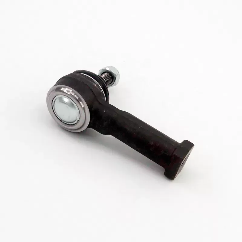
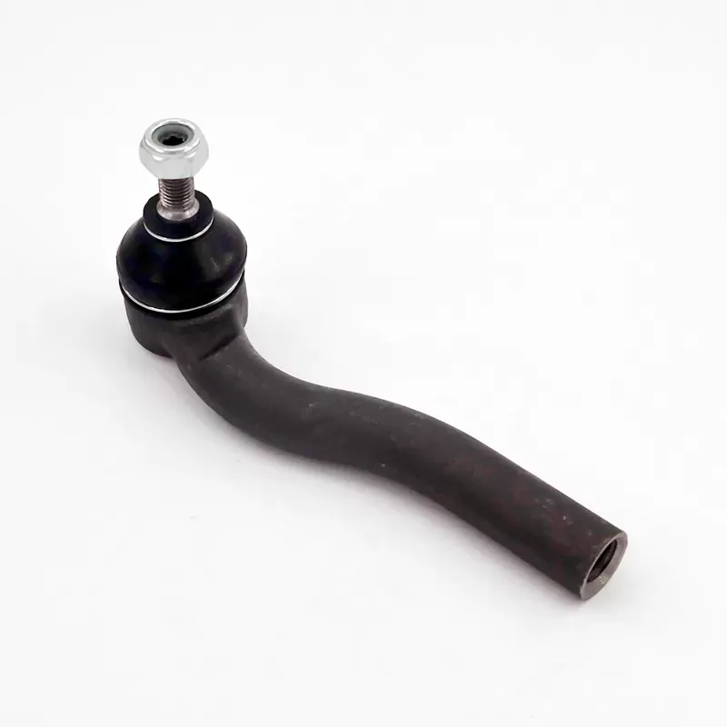
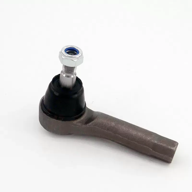
First, I confirm how the component is constructed and what steering function it performs. A typical outer tie rod end contains a ball stud, housing, bearing or socket liner, grease, dust boot, clamp or retaining ring, threaded shank, and sometimes a grease fitting. An inner tie rod end may connect to the steering rack through a ball-and-socket or threaded interface, so its housing, articulation range, rack connection, and axial load path differ from those of an outer component.
The outer tie rod end generally connects to the steering knuckle through a tapered stud and nut. Its threaded shank interfaces with an adjusting sleeve or steering link, and its ball joint must accommodate steering and suspension movement. The inner tie rod end transfers rack movement toward the outer linkage and may experience different axial and angular loads.
I verify the part number, casting or forging marks, thread direction, stud orientation, grease-port location, boot profile, and supplied hardware. I also compare the component against the approved drawing and vehicle application data. A mismatch in thread pitch, taper angle, stud length, or overall assembly height can create installation problems even when the joint feels smooth during a basic hand inspection.
What to Record
- OE reference number and aftermarket supplier part number
- Inner or outer position and vehicle application
- Left-hand or right-hand thread configuration
- Housing material, ball stud material, coating, and heat-treatment condition
- Boot material, clamp type, grease specification, and supplied nut
- Production lot, manufacturing date, inspection date, and operator identification
Why This Matters
Construction determines which tests are meaningful. For example, an outer tie rod end requires close inspection of the tapered stud and steering-knuckle interface, while an inner tie rod end requires attention to rack-end geometry and axial movement. I do not treat both components as interchangeable test articles because their failure modes and installation risks are different.
Step 2 — Perform Visual Inspection for Damage and Assembly Defects
A visual inspection is the fastest way to identify obvious defects, but I treat it as a screening stage rather than complete quality testing. I inspect the housing for cracks, incomplete forming, sharp edges, dents, exposed base metal, casting defects, and inconsistent coating. I inspect the ball stud for scoring, corrosion pits, thread damage, incorrect thread length, damaged taper surfaces, and deformation around the retaining features.
The dust boot receives separate attention because it protects the joint from water, road salt, sand, and abrasive particles. I check for cuts, pinholes, wrinkles that prevent sealing, displaced lips, weak clamps, improper seating, and grease leakage. A boot can look acceptable from the outside while being stretched beyond its working range or trapped under a housing edge.
I also move the joint through its specified articulation range by hand or with a controlled fixture. The movement should not include visible binding, sudden release, grinding, or a loose zone near the neutral position. Hand movement can identify abnormal conditions, but it cannot establish the actual rotational torque, preload, or allowable play.
Common Failure Symptoms and Their Causes
| Symptom |
Possible cause |
Safety or replacement implication |
| Clunk during steering or braking |
Excessive joint clearance, loose nut, worn liner, or damaged stud |
Requires immediate measured inspection and possible replacement |
| Uneven front-tire wear |
Incorrect toe setting caused by bent or dimensionally incorrect linkage |
Verify geometry and alignment after installation |
| Steering wander |
Joint looseness, incorrect length, or poor rack connection |
Inspect the complete steering linkage before vehicle release |
| Torn or displaced boot |
Improper assembly, material aging, over-articulation, or clamp failure |
Replace the joint because contamination can accelerate wear |
| Rust on stud or housing |
Inadequate coating, storage exposure, or salt contamination |
Check corrosion depth and coating process records |
| Stiff or notchy movement |
Surface damage, excessive preload, inadequate grease, or misalignment |
Measure rotational torque before approving the part |
| Thread installation difficulty |
Wrong pitch, burrs, coating buildup, or dimensional error |
Do not force installation; verify with calibrated gauges |
Step 3 — Check Tie Rod End Dimensions, Fitment, and Material Quality
For tie rod end dimensional inspection, I measure every feature that affects fit, alignment, load transfer, or interchangeability. Critical dimensions often include overall length, housing diameter, stud diameter, stud exposed length, taper major and minor diameters, taper angle, thread diameter, thread pitch, threaded length, ball-center height, articulation envelope, and boot seating dimensions.
I use micrometers and gauges for routine production measurements, while a coordinate measuring machine or optical comparator is useful for complex geometry. Thread plug gauges, ring gauges, taper gauges, and go/no-go fixtures provide faster checks at incoming inspection. Measurement systems should be studied for repeatability and reproducibility when the tolerance is narrow or the measurement is safety-critical.
I do not assume that a nominally similar part is interchangeable. A difference of 0.5 mm in overall length can alter toe adjustment range, while a taper mismatch can prevent full seating in the steering knuckle. For each critical feature, I compare measured values with the approved drawing tolerance and calculate capability indices such as Cp and Cpk after collecting a meaningful production sample.
Dimensions I Verify
- Thread pitch, thread direction, major diameter, and effective thread length
- Taper angle, taper depth, stud shoulder position, and nut engagement
- Ball-center height and overall assembly length
- Housing diameter, socket alignment, and retaining-ring position
- Boot lip diameter, clamp compression area, and maximum articulation clearance
- Grease-port position and accessibility when a service fitting is specified
Material and coating inspection should support the dimensional work. I request material certificates for the ball stud and housing, then verify hardness using a defined method such as Rockwell or Vickers testing. If a heat treatment or surface hardening process is specified, the supplier should provide process records and, where required, case-depth or microstructure results.
Coating inspection may include visual coverage, coating thickness measurement, adhesion checks, and corrosion exposure. The test method should be identified in advance because salt-spray duration alone does not prove field life. For corrosion testing, I may use ASTM B117 or ISO 9227 procedures as laboratory references, but the acceptance limit, scribe condition, substrate exposure, and evaluation area must be agreed by the buyer and supplier.
Step 4 — Measure Preload, Rotational Torque, and Joint Movement
Rotational torque testing shows whether the ball stud moves with the intended resistance. I mount the tie rod end in a fixture that reproduces the housing constraint, then rotate the stud through the specified angle using a calibrated torque transducer. I record breakaway torque, running torque, peak torque, and any change in torque after repeated articulation.
A joint with very low torque may have insufficient preload or excessive internal clearance. A joint with very high or irregular torque may have excessive interference, poor surface finish, inadequate lubrication, or misaligned assembly. I compare the measured values with application-specific limits rather than labeling a result acceptable based only on hand feel.
To check tie rod end play, I secure the housing and apply a controlled axial or radial load to the stud. A dial indicator, linear displacement sensor, or electronic gauge measures movement at the specified load and direction. I record both the initial movement and the return movement, because permanent displacement may indicate socket deformation, bearing wear, retaining failure, or stud movement inside the housing.
Play Inspection Procedure
- Clean the joint and confirm that the boot and retaining hardware are installed.
- Mount the housing without distorting the component or restricting normal movement.
- Apply the specified preload or test load using a calibrated force device.
- Measure axial and radial displacement with a resolution suitable for the drawing tolerance.
- Repeat the measurement in at least two orientations when the fixture design permits.
- Compare the result with the approved allowable-play limit and record the lot number.
I also inspect movement for looseness, notchiness, and abnormal angular gaps. If the joint passes a static displacement test but shows inconsistent torque, I do not release it without further examination. Static play and dynamic movement measure different conditions, so both may be required for aftermarket validation.
Step 5 — Perform Load, Articulation, and Durability Tests
Tie rod end durability testing evaluates whether the assembly maintains its function after repeated steering and suspension-related movement. I begin by defining the test load, angle, frequency, number of cycles, temperature, lubrication state, and failure criteria. These values should come from the vehicle duty cycle, customer specification, or a documented engineering model rather than being selected only for convenience.
Axial load testing measures the force required to deform, separate, or pull the ball stud from the housing. To measure tie rod end pull-out strength, I place the assembly in a fixture that supports the housing while applying tensile force along the stud axis. I record the maximum load, displacement curve, failure mode, and whether the failure occurred in the stud, socket, housing, retaining feature, or fixture.
Pull-out strength is not the same as operating load. A component may withstand a specified service load but still require a larger structural safety margin during validation. I therefore define separate criteria for proof load, ultimate pull-out load, permanent deformation, and post-test play. The report should state whether the part remained functional after proof loading or was intentionally tested to failure.
Durability Test Controls
- Apply cyclic axial and angular loads that represent the intended application.
- Record load, displacement, angle, frequency, cycle count, and temperature continuously.
- Stop the test for boot rupture, stud separation, housing cracking, excessive play, or torque loss.
- Measure rotational torque and free play before and after cycling.
- Inspect grease condition, bearing surfaces, retaining elements, and coating after disassembly.
- Photograph each failure and classify the root cause using a defined failure code.
For articulation testing, I move the stud through the specified operating angle while applying representative load. I monitor for interference between the boot, housing, stud, and adjacent fixture components. The test should include both directions of movement when the steering design requires bidirectional articulation.
Fatigue results should be linked to production traceability. If one lot survives 500,000 cycles and another lot fails at 120,000 cycles, the supplier needs to identify differences in heat treatment, forging, machining, lubrication, boot assembly, or process control. A single successful sample is not enough to establish production consistency.
Step 6 — Test Boot Sealing, Contamination, Temperature, and Corrosion
The boot is a functional barrier, not only a protective cover. I test boot sealing by applying articulation, pressure variation, water exposure, and contamination conditions that reflect the intended service environment. After testing, I inspect for leaks, cracks, clamp movement, grease loss, water ingress, and contamination inside the joint.
Contamination testing may use controlled quantities of dust, mud slurry, water, or abrasive particles. The exact medium, concentration, exposure time, temperature, and articulation cycle should be documented. After exposure, I measure torque and play again and inspect the bearing surfaces for scoring or abrasive wear.
Temperature testing addresses material behavior outside normal laboratory conditions. I may condition samples at low and high temperatures, then perform boot articulation, torque, and sealing checks after stabilization. The selected temperature range must match the vehicle region and customer requirement; a generic chamber cycle should not be treated as proof for every climate.
Corrosion resistance testing commonly includes salt-spray exposure using ASTM B117 or ISO 9227 as procedural references. I inspect the housing, stud, threads, clamps, and fasteners at defined intervals, recording red rust, white corrosion products, coating blistering, pitting, and functional changes. The acceptance criterion should specify the maximum permitted corrosion area and whether any corrosion on functional surfaces causes automatic rejection.
Essential Tie Rod End Quality Tests
The core test group should combine inspection methods because no single test identifies every failure mode. Visual inspection finds obvious damage, dimensional measurement confirms fitment, torque testing identifies abnormal internal resistance, and load testing evaluates structural capacity. Durability and environmental testing then show whether the component retains those properties after simulated service exposure.
For a new aftermarket design, I typically divide validation into four levels:
| Test level |
Main purpose |
Typical output |
| Design verification |
Confirm the design meets drawing and engineering requirements |
Dimension, material, torque, load, and failure data |
| Product validation |
Simulate service loads and environmental exposure |
Cycle life, contamination, corrosion, and temperature results |
| Process validation |
Confirm manufacturing can repeat the design |
Capability, gauge studies, first-article, and process records |
| Production inspection |
Detect lot-level variation before shipment |
Sampling results, acceptance decision, and traceability records |
The best tests for aftermarket tie rod ends depend on the risk profile. A direct replacement with an established design may require dimensional, material, torque, load, and sample durability checks, while a modified housing or new boot compound requires broader validation. I prioritize tests according to severity, occurrence, detectability, field history, and the consequences of steering loss.
Step 7 — Use an Aftermarket Tie Rod End Quality Inspection Checklist
I use an aftermarket tie rod end inspection checklist to ensure that inspectors do not focus only on the visible exterior. The checklist should connect each characteristic to a measurement method, specification, sample size, inspection frequency, record format, and reaction plan. Any characteristic classified as critical should have a defined escalation procedure when it fails.
Incoming Inspection Checklist
- Confirm packaging, label, part number, revision, and vehicle application.
- Verify quantity, lot number, production date, and supplier batch identification.
- Check housing, stud, threads, taper, boot, clamps, grease, and supplied hardware.
- Measure critical dimensions against the approved drawing.
- Check thread fit using calibrated go/no-go gauges.
- Measure hardness or review valid material and heat-treatment certificates.
- Record coating condition and thickness where specified.
- Measure rotational torque and free play on the defined sample.
- Photograph nonconforming parts and preserve failed samples for analysis.
- Release, quarantine, sort, rework, or reject the lot according to the control plan.
Sampling plans should be risk-based and documented. For example, a distributor may use tightened inspection for a new supplier, then move to normal inspection only after several accepted lots and verified process capability. AQL values should not replace engineering judgment for safety-related characteristics, and acceptance numbers must be specified before inspection begins.
Step 8 — Evaluate the Tie Rod End Supplier’s Quality System
A Tie Rod End Supplier should provide more than a test report for a small number of samples. I evaluate material certificates, incoming inspection records, forging or machining controls, heat-treatment records, coating controls, assembly torque data, boot installation checks, final inspection, and nonconformance handling. The supplier should also maintain lot traceability from raw material through finished packaging.
For supplier qualification, I request a control plan, process flow diagram, PFMEA, work instructions, inspection standards, calibration records, and sample validation reports. Capability studies for critical dimensions should include the measured dataset, specification limits, calculation method, and subgroup structure. A Cpk value without the underlying measurement conditions does not show whether the process is stable.
I also review delivery risk because quality compliance and supply continuity are connected. A supplier that cannot identify production lots may make field containment difficult, while a supplier with only one unverified process route may face extended delays after a tooling or equipment failure. I ask for stated lead times, minimum order quantities, safety-stock arrangements, production capacity, corrective-action timing, and documentation retention periods.
Zegao Machinery is a relevant example of a manufacturer operating in the automotive chassis-parts sector. Its company information identifies a Yuhuan, Zhejiang facility established in 1995, with a stated factory area of 5,000 square meters, more than 3,000 square meters of construction area, fixed assets of 30 million yuan, working capital of 20 million yuan, and annual output value of 60 million yuan. Its product scope includes tie rod ends, ball joints, control arms, shock absorbers, and other chassis components.
Those company figures are useful for initial supplier screening, but they do not replace part-specific validation. When I assess Zegao Machinery or another Tie Rod End Supplier, I still require dimensional reports, material evidence, process capability data, sample test results, lot traceability, and an agreed corrective-action process. Supplier size and product range provide context; measurable acceptance records determine whether a specific part can be approved.
Step 9 — Analyze Failure Modes Before Approving Replacement Parts
Failure analysis helps connect test results with actual service risks. Common tie rod end failure modes include ball stud fracture, socket pull-out, liner wear, housing cracking, thread stripping, boot tearing, clamp release, corrosion pitting, grease loss, and excessive axial or radial play. Each failure mode should be linked to a likely cause, detection method, containment action, and replacement decision.
A cracked housing or damaged ball stud is normally a rejection condition because structural integrity has been compromised. Excessive play requires measurement against the approved limit, but any looseness accompanied by clunking, visible movement, or steering instability should trigger immediate vehicle-level inspection. A torn boot may require replacement even if the joint currently has acceptable torque because contamination can accelerate wear after installation.
After a failed component is found in the field, I preserve the returned part, installation hardware, packaging, and vehicle information when available. I record mileage, operating region, road conditions, installation date, torque method, alignment history, and reported symptoms. This information helps distinguish part failure from improper installation, impact damage, incorrect application, or unrelated steering-system defects.
Economic Benefit Analysis: Why Structured Testing Reduces Total Cost
The cost of testing should be compared with the cost of returns, sorting, warranty labor, expedited replacement, vehicle downtime, and loss of customer confidence. A simple total-cost model is:
Total cost = inspection cost + laboratory validation cost + failure containment cost + warranty cost + field replacement cost + delivery disruption cost.
For example, if a distributor receives 10,000 tie rod ends and a 2% defect rate creates 200 suspect units, the financial effect includes sorting all affected inventory, shipping replacement parts, processing returns, and possibly compensating repair facilities. Reducing the defect rate from 2% to 0.5% prevents 150 suspect units in that example, before accounting for vehicle-level labor and freight.
I also examine the cost of delayed delivery. If a critical part is unavailable for 10 business days and a customer requires 300 units per day, the exposure is 3,000 units of delayed demand. A supplier-quality agreement with traceability, retained samples, and defined reaction times can reduce the number of lots requiring full inventory quarantine.
Testing equipment has a similar economic trade-off. A supplier may justify a torque tester, force frame, or optical measurement system when the equipment reduces external laboratory fees and detects defects before shipment. The return should be calculated from annual test volume, equipment cost, calibration expense, operator time, avoided returns, and expected reduction in destructive failures.
How to Choose Tie Rod End Quality Tests
I select tests according to the component’s risk and the decision being made:
| Decision |
Priority tests |
Evidence required |
| Incoming shipment approval |
Visual, dimensions, threads, torque, play, packaging |
Signed inspection report and lot traceability |
| New supplier qualification |
Full dimensions, hardness, coating, load, torque, boot sealing |
Material records, capability data, validation report |
| Design change approval |
Comparative dimensions, torque, fatigue, temperature, contamination |
Before-and-after results with change control |
| Field failure investigation |
Play, pull-out, fracture analysis, boot inspection, corrosion review |
Returned-part report and containment record |
| High-volume production release |
Sampling inspection, capability studies, process audits |
Control plan, SPC records, corrective-action history |
I avoid using one pass/fail number for every vehicle application. Thread dimensions, taper geometry, articulation angle, preload, rotational torque, pull-out strength, and allowable play must be tied to the relevant engineering specification. When no customer limit exists, the supplier and buyer should establish a documented engineering rationale before production approval.
Conclusion
How to Test Tie Rod End Quality for Aftermarket Applications requires more than checking whether the joint looks clean or moves by hand. I recommend starting with application identification, construction review, dimensional inspection, thread and taper verification, material and coating checks, torque measurement, controlled play testing, axial load testing, and pull-out evaluation. For new designs or changed materials, I add fatigue cycling, boot durability, contamination, temperature, and corrosion testing.
The next step is to convert these requirements into a supplier-specific control plan. Define critical dimensions, allowable play, torque limits, proof loads, durability cycles, environmental exposure conditions, sampling rules, and lot acceptance criteria before placing production orders. Then require the Tie Rod End Supplier to provide traceability, material certificates, capability studies, calibration records, and corrective-action documentation.
Zegao Machinery can be included in an aftermarket sourcing review for tie rod ends and related chassis parts, but approval should depend on measurable evidence for the exact part number and application. By combining laboratory validation with production-lot inspection, I can reduce fitment errors, identify steering safety risks earlier, manage delivery interruptions, and control the total cost of ownership.


 es
es cn
cn