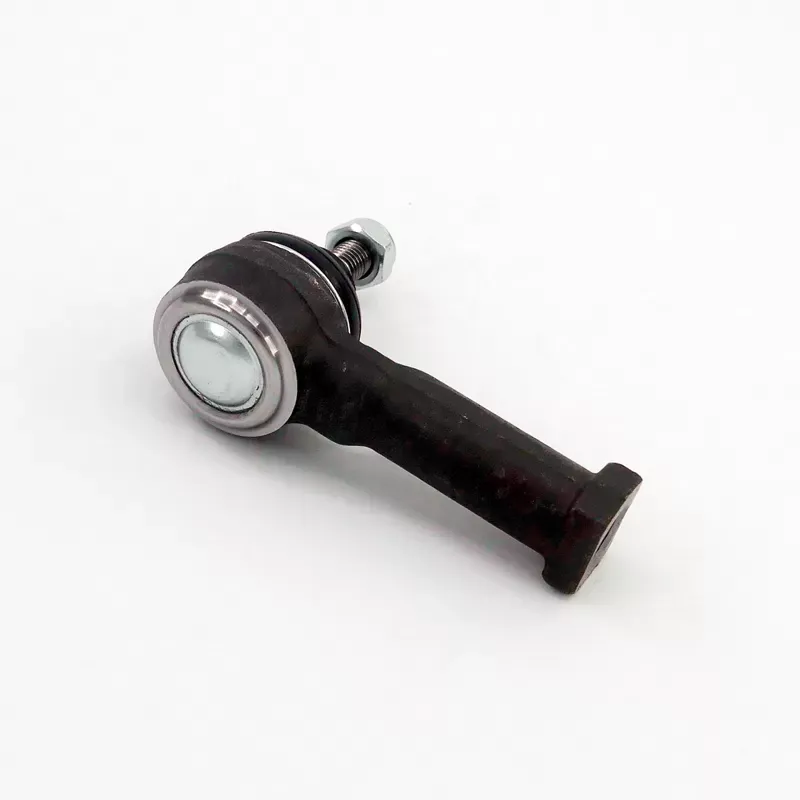
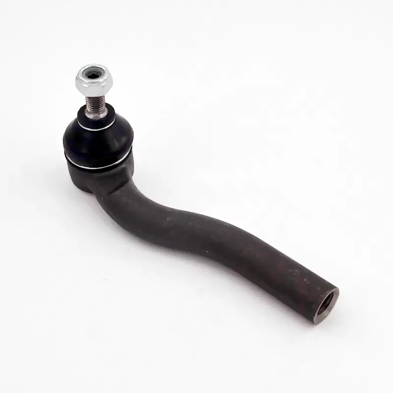
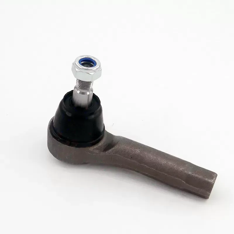
Tie rod ends are manufactured through a controlled sequence of steel selection, heating, forging or upsetting, machining, threading, heat treatment, surface protection, assembly, and inspection. I describe the process as a factory-to-field chain because each stage affects steering accuracy, fatigue life, corrosion resistance, installation fit, and total replacement cost.
- Select certified steel according to load, geometry, corrosion exposure, and connection design.
- Heat billets or bar stock before closed-die forging, hot pressing, or upsetting.
- Form the ball stud, rod end, or housing while controlling grain flow and material fill.
- Trim flash, machine bearing surfaces, roll or cut threads, and create locating features.
- Apply hardening and tempering to achieve the required strength, hardness, and toughness.
- Add plating, phosphate, coating, or other corrosion-control treatments.
- Assemble the ball stud, socket, bearing, grease, retaining components, and rubber boot.
- Verify dimensions, torque, hardness, tensile performance, fatigue resistance, corrosion protection, and traceability.
Automotive tie rod ends differ from structural tie rod assemblies used in buildings, bridges, and industrial frames. Automotive parts require compact steering joints, angular movement, low friction, sealed lubrication, and resistance to road shock, while structural tie rods usually prioritize axial tension capacity, anchor compatibility, and long exposed-service corrosion protection.
!
What Is a Tie Rod End and How Does It Work?
A tie rod end is a steering linkage joint that connects the steering rack or center link to the steering knuckle. It normally combines a threaded shank with a ball-and-socket joint, allowing the steering knuckle to move through suspension travel while transmitting steering force from the rack. The ball stud rotates and articulates inside a housing, bearing, or polymer-lined socket.
The joint must perform two functions at the same time. It must transmit axial and lateral loads without excessive deformation, and it must permit angular movement without binding. A passenger vehicle tie rod end may experience repeated shock loading from potholes, braking, cornering, and curb impacts, so the manufacturing process must control both static strength and fatigue behavior.
Tie rod ends are related to ball joints but serve different positions in the vehicle. A ball joint primarily connects a control arm to the steering knuckle and supports suspension articulation, while a tie rod end transfers steering movement. The two components may use similar ball-stud principles, but their dimensions, preload, movement range, sealing arrangement, and load case are not automatically interchangeable.
How Are Tie Rod Ends Manufactured? The Complete Production Process
The production sequence begins with an engineering drawing and application review. Before selecting equipment, I would confirm the vehicle platform, left- or right-hand configuration, thread specification, ball-stud diameter, taper angle, articulation range, target service load, corrosion environment, and annual volume. A component designed for a light passenger vehicle may use a different process window from one intended for a commercial van, off-road vehicle, or heavy-duty truck.
| Manufacturing stage |
Main equipment |
Typical control points |
Common output |
| Material preparation |
Saw, bar straightener, spectrometer |
Chemistry, diameter, heat number |
Certified billets or bars |
| Heating |
Induction or gas furnace |
Temperature uniformity, scale control |
Forging-ready blanks |
| Forming |
Mechanical or hydraulic press, dies |
Fill, grain flow, flash, die wear |
Near-net forged part |
| Trimming |
Trimming press, punch and die |
Flash removal, edge cracks |
Clean forging |
| Machining |
CNC lathe, mill, broach, grinder |
Taper, threads, runout, surface finish |
Finished metal component |
| Heat treatment |
Quench and temper line |
Hardness, distortion, microstructure |
Strengthened part |
| Surface protection |
Zinc plating, phosphate, coating line |
Thickness, adhesion, salt-spray result |
Corrosion-protected part |
| Assembly |
Press, torque tools, boot station |
Preload, torque, boot seal, grease fill |
Completed tie rod end |
| Inspection |
CMM, gauges, torque tester, fatigue rig |
Dimensions, function, traceability |
Accepted or rejected assembly |
What Materials Are Used to Manufacture Tie Rod Ends?
Most automotive tie rod ends use medium-carbon or alloy steel selected for strength, toughness, forgeability, and heat-treatment response. Common material families include carbon-manganese steels and chromium-molybdenum alloy steels, but the exact grade depends on the load case and customer drawing. The ball stud and housing may use different grades because the stud requires surface wear resistance and core toughness, while the housing must support the socket and resist deformation.
Material certification should identify the heat number, chemical composition, mechanical properties, and applicable standard. Incoming inspection commonly includes hardness screening, visual inspection, dimensional verification, and periodic optical-emission spectroscopy. For safety-related steering components, a supplier should also maintain a material traceability link from the steel batch to the forged lot, heat-treatment batch, machining route, and final assembly record.
Steel chemistry affects both production and field behavior. Excessive carbon can reduce weldability and increase cracking risk during forming or hardening, while inadequate alloy content may limit hardenability in larger sections. A purchasing specification should therefore define the material grade, delivery condition, certification requirements, test frequency, and acceptance limits rather than simply stating “forged steel.”
Tie Rod End Forging Process: From Billet to Near-Net Shape
The tie rod end forging process usually starts with bar stock or cut billets. The material is cut to a controlled mass because an undersized billet can cause incomplete die fill, while an oversized billet increases flash, forming force, and trimming waste. For repeatable production, billet weight variation should be controlled tightly enough that the forged volume remains within the die’s designed fill range.
Heating may use induction equipment for rapid, localized heating or a furnace for batch production. The process window depends on the steel grade and forming method, but many hot-forging operations use a temperature range of approximately 950–1,200°C. The actual target must come from the material and die design because excessive temperature can produce scale, grain coarsening, or decarburization, while insufficient temperature can raise press load and create laps or incomplete filling.
The heated billet is placed into a preforming die and then a finishing die. Upsetting increases material flow into the ball or flange region, while closed-die forming establishes the outer profile, taper, neck, and mounting features. Proper die design keeps the grain flow aligned with the major load path, which can improve fatigue resistance compared with a part produced only by extensive material removal.
Why Are Tie Rod Ends Made Using Forging Instead of Casting?
Forging is commonly selected for automotive tie rod ends because it compresses and redirects the steel structure under controlled deformation. The process can produce continuous grain flow, lower internal void risk, and a compact part with predictable mechanical properties after heat treatment. Casting may be suitable for some geometries, but it introduces different risks, including shrinkage porosity, inclusions, gas defects, and variable local density.
The choice is not universal. Forging requires dies, heating equipment, trimming tools, and process development, so initial tooling cost can be significant. For low-volume prototypes or complex non-safety-critical shapes, machining from bar or a hybrid process may be financially practical, even though material utilization and cycle time may be less favorable.
I would compare the methods using five measurable factors: annual volume, part geometry, required strength, tolerance, and total cost. A forged blank may reduce machining time by 30–60% compared with machining the entire shape from bar, but the saving depends on the component profile and tooling amortization. Casting should be rejected when porosity or inconsistent fatigue performance cannot be controlled to the application requirement.
Defect Mechanisms During Forming
Forging defects are usually related to material flow, temperature, die condition, lubrication, or billet preparation. Uneven flange thickness can result from eccentric billet placement, unbalanced die filling, or incorrect preform volume. Corrective actions include checking billet centering, measuring preform mass, reviewing die alignment, and adding sectional inspection at the flange and transition zones.
Laps and cold shuts occur when metal folds over itself instead of joining correctly. These defects may originate from low forming temperature, excessive friction, poor preform design, or sharp die transitions. Die-radius revision, improved lubrication, temperature monitoring, and reduced material displacement per hit can reduce the risk.
Cracking may appear at the neck, flange edge, or highly deformed section. Causes include excessive reduction, unfavorable steel chemistry, surface scale, low temperature, or an unsuitable heat-treatment cycle. Magnetic particle inspection after forging or after machining can help detect surface-connected cracks, but process correction is preferable to relying only on final sorting.
Tie Rod End Machining and Heat Treatment
After forging and trimming, the part enters machining. CNC turning can establish the shank diameter, shoulder, socket reference, and other rotational features, while milling or drilling creates flats, holes, grease passages, or assembly locations. Tapered ball studs require controlled taper angle, diameter, and surface finish because the connection must seat correctly in the steering knuckle.
Thread production may use thread rolling or thread cutting. Thread rolling displaces material and can improve surface continuity and fatigue behavior when the blank diameter, roller profile, and alignment are correct. Thread cutting provides flexibility for prototypes and low-volume parts but removes material and may expose machining marks that require additional control.
Thread damage is a frequent source of assembly rejection. It may be caused by incorrect blank size, worn dies, chip accumulation, poor chamfering, tool misalignment, or excessive clamping force. A practical inspection plan should include go/no-go gauges, visual checks at the thread runout, and periodic measurement of pitch diameter rather than relying only on a final nut-fit test.
Heat treatment normally includes austenitizing, quenching, and tempering for the steel component. The exact cycle depends on material grade, cross-section, and required mechanical properties, but the key controls are furnace temperature, soak time, quench condition, transfer time, tempering temperature, and part loading. Hardness alone is not sufficient because two parts can show similar surface hardness while having different core toughness or microstructure.
A typical automotive steering component specification may define a hardness window such as approximately 28–38 HRC for a tempered alloy-steel part, but the drawing or validated process specification must control the final value. Excessive hardness can increase brittleness and cracking susceptibility, while insufficient hardness may reduce wear resistance and deformation resistance. Distortion after quenching is controlled through fixture design, agitation management, loading orientation, and post-treatment straightening where permitted.
Machining and Heat-Treatment Control Plan
| Control item |
Recommended record |
Why it matters |
| Ball-stud taper |
CMM or dedicated taper gauge result |
Ensures knuckle fit and clamping |
| Thread pitch diameter |
Caliper, thread micrometer, or air gauge |
Controls nut engagement and preload |
| Ball diameter |
CMM or profile gauge |
Controls articulation and bearing contact |
| Runout |
Dial indicator or CMM |
Reduces eccentric steering movement |
| Hardness |
Rockwell or Vickers test |
Confirms heat-treatment response |
| Microstructure |
Metallographic sample by lot |
Detects improper quench or temper |
| Surface finish |
Profilometer reading |
Limits friction and wear initiation |
| Straightness |
Fixture or CMM measurement |
Prevents installation and alignment errors |
Surface Protection, Sealing, and Assembly
Corrosion protection begins with surface preparation. Oil, scale, machining residue, and abrasive contamination must be removed before phosphate, zinc plating, e-coating, or another specified treatment. Coating thickness should be measured at defined locations because a thick coating in one area does not prove adequate coverage in threads, recesses, shoulders, or contact zones.
For exposed automotive parts, corrosion testing may use neutral salt spray as a comparative process check. A customer specification might require several hundred hours without red rust on selected surfaces, but the required duration and rating should be agreed before production because salt-spray hours do not directly equal road-service years. Coating adhesion, hydrogen embrittlement control for high-strength steel, and thread compatibility also require separate checks.
Assembly begins after metal parts have passed dimensional and surface inspections. The ball stud, bearing, socket, grease, washer, retaining ring, plug, and boot are installed in a defined order, usually with a press or controlled assembly machine. Press force, seating depth, rotational torque, articulation torque, and axial play should be recorded by lot or by part, depending on the customer’s control plan.
The rubber boot is more than a protective cover. It keeps water, dust, and road salt away from the ball-and-socket interface while retaining grease inside the joint. Installation defects include a twisted boot, incomplete seating, puncture, excessive clamp force, and poor sealing at the small or large diameter, so visual inspection should be combined with a controlled leak or retention check when required.
Final assembly may include a castle nut, prevailing-torque nut, cotter pin, jam nut, or other locking arrangement. Installation torque and thread engagement must match the vehicle design because under-torque can permit movement, while over-torque can damage threads, distort the joint, or increase articulation torque. The production record should identify the torque tool, calibration status, tightening value, operator or station, and any rework.
Tie Rod End Quality Control and Testing
A factory-to-field quality framework connects incoming steel, forming, machining, heat treatment, coating, assembly, and vehicle installation. I would establish a control plan that identifies each characteristic as critical, major, or standard, then assign a measurement method, sampling frequency, reaction plan, and traceability requirement. A process capability target such as Cpk ≥ 1.33 is often used for stable critical dimensions, although the customer drawing or quality agreement may specify a different threshold.
Material inspection should begin with the mill certificate and heat-number verification. Periodic chemical analysis confirms that the delivered steel matches the approved grade, while hardness and visual checks identify incorrect material condition or handling damage. If a material mix-up is discovered, the affected lot should be quarantined and traced before any forging or machining operation continues.
Dimensional inspection covers the ball diameter, taper, shank length, thread dimensions, mounting height, housing diameter, flange thickness, articulation angle, and overall envelope. A coordinate-measuring machine is useful for first-article validation, while dedicated gauges are faster for production checks. Measurement-system analysis should verify that the gauge can distinguish a conforming part from a nonconforming part; a gauge repeatability and reproducibility result below 10% is a common target.
Mechanical testing must reflect the actual failure modes. Tensile or pull-out testing checks whether the ball stud or assembled joint can withstand axial separation loads, while torque testing evaluates rotational resistance and breakaway behavior. Fatigue testing applies repeated angular or axial cycles to identify wear, plastic deformation, boot failure, or fracture that may not appear in a single static test.
Non-destructive testing can include magnetic particle inspection for ferromagnetic forged steel. It is useful for detecting surface and near-surface cracks around the neck, flange, and transition areas. Ultrasonic inspection may be considered for larger sections or where internal discontinuities are a concern, but the method, calibration block, sensitivity, and acceptance criteria should be written into the inspection procedure.
Corrosion testing should evaluate both the coating and the assembled joint. A salt-spray chamber may expose coated samples or finished assemblies, while cyclic corrosion testing can provide a more representative combination of salt, humidity, drying, and temperature changes. The inspection report should state exposure duration, surface rating, test location, coating thickness, and whether red rust, blistering, flaking, or thread seizure occurred.
| Quality area |
Example acceptance target |
Corrective response |
| Critical dimensional capability |
Cpk ≥ 1.33 |
Adjust tool offset, die, or fixture |
| Thread inspection |
100% go/no-go gauge check |
Quarantine lot and inspect die wear |
| Hardness |
Drawing-defined range, for example 28–38 HRC |
Review furnace and quench records |
| Surface coating |
Drawing-defined thickness, for example 8–15 μm |
Recheck cleaning and bath control |
| Assembly torque |
Customer-defined value, recorded by station |
Calibrate tool and reverify joint |
| Magnetic particle inspection |
No rejectable linear indications |
Contain lot and investigate forging |
| Fatigue performance |
Validated cycle and load requirement |
Review material, preload, and heat treatment |
| Traceability |
Heat, forging, machining, treatment, assembly lot |
Block shipment if records are incomplete |
How Manufacturing Changes by Application and Connection Design
Tie rod end manufacturing varies substantially according to the vehicle and connection arrangement. An outer tie rod end with a tapered stud may require strict control of taper geometry and stud hardness, while an inner tie rod connection may use a threaded socket, rack interface, or locking feature with different machining priorities. A commercial vehicle part may require a larger cross-section, stronger housing, higher pull-out capacity, and more intensive fatigue validation.
The load case also changes the best process route. A compact, high-volume passenger-car part generally favors closed-die forging followed by automated machining and assembly because tooling cost can be spread across many units. A low-volume custom part may use a forged preform with more CNC machining, or machining from alloy-steel bar when tooling investment cannot be justified.
| Requirement |
Preferred method |
Main trade-off |
| Large annual volume |
Closed-die forging plus automated machining |
Higher tooling cost, lower unit cost |
| Low annual volume |
CNC machining or hybrid forging |
Higher material waste or cycle time |
| High fatigue load |
Forging with controlled grain flow |
Requires die development and validation |
| Complex non-repeating geometry |
CNC or multi-stage hybrid process |
More machining time |
| Tight taper and thread tolerances |
Forging followed by precision machining |
Additional inspection and tool control |
| Corrosive operating environment |
Forged steel plus validated coating system |
Coating cost and hydrogen-risk management |
| Prototype or sample batch |
Machined blank or simple preform |
Not always economical for mass production |
Choosing a Tie Rod End Supplier
When I evaluate a Tie Rod End Supplier, I separate product claims from documented manufacturing controls. The supplier should provide material certificates, drawing revision control, first-article reports, process-flow diagrams, heat-treatment records, coating data, dimensional results, and test reports. I also check whether the supplier can connect a field complaint to a specific production lot within a defined response period.
Production capacity should be discussed using measurable information. Ask for press tonnage, CNC machine count, heat-treatment batch size, assembly stations, inspection equipment, normal monthly output, and peak capacity after overtime or additional shifts. Delivery risk is easier to estimate when the supplier provides tooling lead time, raw-material procurement time, approval milestones, safety-stock policy, and a documented contingency plan.
A manufacturer serving OEM and aftermarket steering components should also clarify the difference between catalog parts and custom tie rod end manufacturing. Catalog production may offer shorter approval cycles, while custom parts require drawing review, prototype samples, fixture development, validation testing, packaging approval, and a production-part approval process. The lowest quoted unit price can become expensive if a late design change requires new dies or if inconsistent dimensions create installation returns.
Zegao Machinery as a Supplier Evaluation Example
Zegao Machinery, also identified as Yuhuan Zegao Machinery Company, presents itself as a chassis-parts manufacturer and supplier based in Yuhuan, Zhejiang Province, China. Company information states that it was established in 1995, operates on a 5,000-square-meter site with more than 3,000 square meters of construction area, and reports fixed assets of 30 million yuan, working capital of 20 million yuan, and annual output value of 60 million yuan.
Its listed product range includes tie rod ends, ball joints, control arms, shock absorber parts, stabilizer links, rack ends, and other suspension or chassis components. For a purchasing team, that product breadth may support multi-part sourcing, but it also makes product-specific validation necessary. I would request tie rod end drawings, material grades, forging route, heat-treatment parameters, coating specification, test capacity, and recent lot-level inspection records before approving a new program.
Zegao Machinery also describes custom product support. In practice, a custom project should be evaluated through defined milestones: technical drawing review, tolerance confirmation, prototype or sample production, functional testing, packaging approval, pilot production, and serial-production capability review. A supplier’s location, facility size, or stated output does not replace dimensional, mechanical, corrosion, and traceability evidence for the specific tie rod end being purchased.
Production Cost, Lead Time, and Total Cost of Ownership
Tie rod end manufacturing cost is divided into material, forging, tooling, machining, heat treatment, coating, assembly, inspection, packaging, logistics, and warranty exposure. Tooling may represent a large share of the initial project cost, particularly when the ball stud and housing require several forming stages. At higher volumes, the tooling cost per part decreases, while automated machining and assembly can reduce labor content.
A practical quotation should show assumptions rather than only a unit price. I would ask for annual volume, material yield, scrap allowance, inspection frequency, packaging quantity, minimum order quantity, payment terms, and delivery basis. If a forged blank uses 1.2 kg of steel but the finished part weighs 0.85 kg, the 0.35 kg difference contributes to flash, trimming loss, machining allowance, and recycling value.
Lead time should be divided into separate phases. A repeat catalog part may require material purchasing, production scheduling, inspection, and shipment, while a custom part may add 4–10 weeks for die design, sample production, testing, and approval depending on complexity. Delivery risk can be reduced through approved secondary steel sources, defined safety stock, dual cavity or spare-die planning, and forecast visibility rather than through a single promise of rapid delivery.
Total cost of ownership includes more than purchase price. A part that costs 8% less but produces a 2% installation rejection rate may be more expensive than a part with a higher price and a 0.3% rejection rate. For a fleet purchasing 20,000 units annually, reducing avoidable rejection by 1.7 percentage points prevents approximately 340 rejected units before considering labor, freight, inspection, and customer-service costs.
Service life is also connected to material selection and corrosion protection. A boot leak, thread seizure, coating failure, or fatigue crack can create replacement labor and vehicle downtime that exceed the initial component price. For this reason, I would compare suppliers using warranty returns per million parts, field mileage data, fatigue results, corrosion results, and installation-related complaints.
Sustainability and Corrosion Reduction
Sustainability improvements in tie rod end production usually come from material efficiency, energy control, scrap recovery, coating management, and longer replacement intervals. Closed-die forging can reduce the amount of machining waste compared with producing the entire component from bar, although flash and trimming scrap still need to be collected and recycled. Induction heating may also reduce heating time and localized energy loss when the production volume supports stable equipment utilization.
Weathering steel and alternative corrosion-resistant materials require application-specific evaluation. A material that performs well in an atmospheric structural environment may not be suitable for a compact automotive joint exposed to salt, water, vibration, and stone impact. The correct comparison should include tensile and fatigue properties, coating compatibility, galvanic interaction, machinability, heat-treatment response, and lifecycle replacement frequency.
Corrosion reduction should be measured through coating thickness, adhesion, cyclic or salt-spray exposure, and field inspection. A thin coating that fails at a machined shoulder or thread root can expose the base steel and increase seizure risk. Better results come from controlling cleaning, pretreatment, bath chemistry, rinsing, drying, masking, and post-treatment rather than simply increasing coating thickness.
Practical Manufacturing Checklist
Before approving a tie rod end manufacturing program, I use the following checklist:
- Confirm the vehicle application, load case, articulation angle, and connection design.
- Approve the steel grade, chemical limits, mechanical properties, and material certificate format.
- Review billet diameter, cut length, mass tolerance, heating method, and forging temperature window.
- Validate die fill, flange thickness, grain flow, flash control, and trimming quality.
- Define machining datums, taper tolerance, thread class, runout, surface finish, and inspection method.
- Approve hardening, quenching, tempering, hardness range, microstructure, and distortion limits.
- Specify coating type, thickness, adhesion, hydrogen-embrittlement controls, and corrosion-test duration.
- Validate bearing or socket design, grease quantity, boot material, clamp retention, and articulation torque.
- Establish tensile, pull-out, torque, fatigue, NDT, corrosion, and final dimensional testing.
- Require lot traceability from steel heat number through shipment packaging.
- Compare tooling amortization, unit price, rejection rate, warranty exposure, and delivery risk.
- Confirm pilot-run results before releasing serial production.
Conclusion
How Are Tie Rod Ends Manufactured? The answer is a controlled progression from certified steel and billet preparation to forging, trimming, CNC machining, thread production, heat treatment, surface protection, assembly, and final testing. Forging is commonly selected for automotive steering parts because it can provide favorable grain flow and efficient material use, but the correct process still depends on geometry, load case, volume, tolerance, and cost.
For engineers and purchasing teams, the most important evidence is not a general product description. It is the documented connection between material certificates, forging parameters, machining records, heat-treatment results, coating thickness, assembly torque, dimensional capability, fatigue performance, corrosion testing, and field returns. When assessing a Tie Rod End Supplier such as Zegao Machinery, I would review its stated manufacturing scope and custom capabilities, then require part-specific validation records before approval.
The final decision should use total cost of ownership rather than unit price alone. A supplier that controls defects, delivery variation, installation preload, and traceability can reduce rejected parts, warranty exposure, vehicle downtime, and premature replacement requirements across the service life of the steering system.


 es
es cn
cn